Metrology
Why a FARO Arm Measures One Outside Diameter Incorrectly
A single incorrect diameter often points to a feature-specific setup or probing issue rather than a general arm calibration problem — the first step below is how to tell the difference before you chase the wrong cause.
1. Verify with a known reference
Before chasing a feature-specific cause, confirm this actually is one. Check the same shaft with a micrometer or vernier caliper, or measure a calibrated ring gauge, sphere, or another known-good OD with the arm itself.
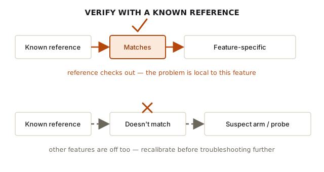
If every other feature and the known reference check out and only this one diameter is wrong, the cause is local to this feature's setup or probing — proceed with the steps below. If the known reference is also off, or other features are inconsistent too, suspect the arm or probe before anything else. That points toward accuracy verification and recalibration, not the feature-specific checks that follow.
2. Confirm the feature type
Make sure PolyWorks defines the measured feature as an external cylinder. An internal-cylinder definition can apply probe compensation in the wrong direction.
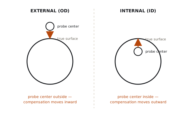
A FARO arm reports the position of the probe tip's center, not the point where it actually touches the part. For a spherical probe on an external (OD) surface, the ball's center sits one probe radius outside the true contact point, so compensation has to move the reported point inward, toward the part, to recover the true surface. For an internal (ID) feature it works the other way: the probe center sits inside the bore, so compensation moves outward, toward the wall. Which direction the software applies depends entirely on whether the feature is defined as external or internal. Get it backwards and the software doesn't just skip the correction — it applies it the wrong way. In the idealized case that can push the reported diameter off by close to twice the probe diameter, though the exact size of the error depends on the software's fitting mode and how the feature was defined.
3. Verify the calibrated probe
Verify that the correct calibrated probe is selected in the software and that its ball diameter matches the probe physically installed on the arm.
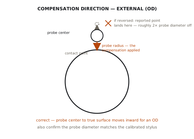
This is a different check from feature type. Feature type controls which direction compensation is applied; probe diameter controls how large that correction is. Compensation itself is about determining the probe tip's center relative to the arm's coordinate system, so a mismatched probe diameter is a separate failure mode from a wrong-direction error — it shifts the diameter by a fixed amount rather than flipping its sign, which is why it's worth checking independently rather than assuming one fix covers both.
In some manual probing workflows, the direction the probe is withdrawn, or the compensation mode selected by the operator, can affect which side of the surface the software interprets the contact point to be on. If a feature comes back consistently over or under nominal in the same direction — not scattered — that's the signature of a compensation-side error rather than random point noise.
This isn't a universal rule built into PolyWorks, so don't treat it as one. If compensation looks reversed, repeat the feature while deliberately controlling probing direction, and check the compensation indicator in the software rather than relying on a fixed habit.
4. Review point distribution
Take points around the full circumference and at more than one height. Avoid collecting most points from one side.
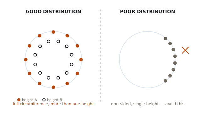
A cylinder fit solves for two things at once: a radius and an axis — a line in space, not just a circle. Points taken from a narrow arc leave that axis direction weakly constrained, so several noticeably different cylinders can fit the same limited data almost equally well by the software's own residual score. Spreading points across the full circumference and across more than one height constrains both the radius and the tilt of the axis, which is what makes a fit trustworthy rather than merely low-residual.
5. Inspect the surface
Paint, burrs, surface roughness, chamfers, and edge contact can shift the fitted diameter.
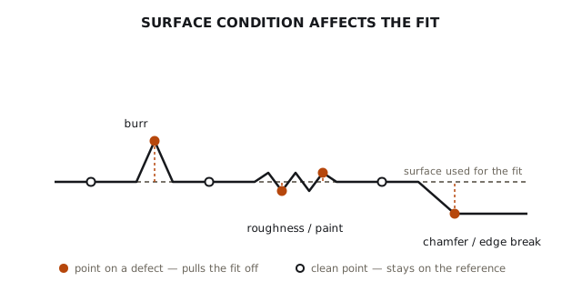
A point that lands on a burr, a paint buildup, or a chamfer isn't measuring the true cylindrical surface at all — it's measuring whatever local feature happens to be there, and that can influence the fitted result. PolyWorks offers weighting, constraint, and other best-fit options that can reduce this influence, but the simplest fix is upstream of any of that: avoid collecting points on visibly damaged, contaminated, or non-cylindrical areas in the first place.
6. Test with individual points
Create a new cylinder from manually selected individual points. This helps identify whether the issue comes from the measurement method or feature settings.
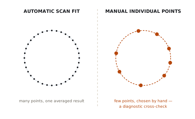
This step is a diagnostic, not a fix. If a small set of hand-picked points produces roughly the same diameter as the full automatic scan, the fitting math is doing its job and the error is upstream — feature type, compensation, or probe calibration. If the manual fit disagrees noticeably with the scan, the problem is more likely in the point cloud itself or in how the automatic feature was defined. And if this feature is the only one that's wrong while a known reference measured correctly in Step 1, that's confirmation the cause was local all along.